Teaching:TUW - UE InfoVis WS 2007/08 - Gruppe 02 - Aufgabe 1 - Flow Visualization: Difference between revisions
mNo edit summary |
No edit summary |
||
| (6 intermediate revisions by 3 users not shown) | |||
| Line 1: | Line 1: | ||
Flow visualization is a process of making the physics of fluid flows visible in oder to analyse it. | |||
== | == Definition == | ||
{{Quotation|To be able to recognize the motion of the fluid, one must therefore provide a certain technique by which the flow is made visible. Such methods are called flow-visualization techniques.|[Merzkirch, 1987]}} | |||
== Overview == | |||
Flow visualization is a modern technique to visualize motions and patterns of mostly invisible fluids, e.g. gas, air or water. | |||
Main target is to make flows in a specific context visible so that it can be analyzed. | |||
Although the basic task for flow visualization is revealing the flow within fluids, it may offers an additional benefit. It does not only make flows visible, it can also be used as a method for simulating flows and the interaction of objects within fluids. So it is also a simulation technique and therefore, it can be classified as a method for [[Scientific Visualization]]. | |||
Application areas for flow visualization are e.g. in aviation, aqua- or aerodynamic. | |||
In fact, there are several ways how to do this. Generally we can divide into two main methods: | In fact, there are several ways how to do this. Generally we can divide into two main classes of methods: | ||
[[Image:e398-inflatable.jpg|right|thumb|150px|Figure 1]] | [[Image:e398-inflatable.jpg|right|thumb|150px|Figure 1]] | ||
[[Image:2-01-AERO-Papodopoulos.jpg|right|thumb|150px|Figure 2]] | [[Image:2-01-AERO-Papodopoulos.jpg|right|thumb|150px|Figure 2]] | ||
[[Image:HyFish.jpg|right|thumb|150px|Figure 3]] | [[Image:HyFish.jpg|right|thumb|150px|Figure 3]] | ||
=== Physical methods=== | |||
Physical methods are an experimental approach on flow visualization. Basically these techniques can further be divided into three groups [Löffelmann, 1998]: | |||
* Adding foreign material | |||
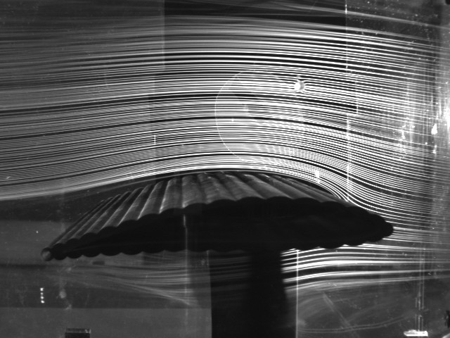
:These methods work by adding small particles, e.g. smoke or oil, to the fluid to make it visible. Figure 1 gives an example for using smoke in a wind tunnel. | |||
* Optical techniques | |||
:These methods work e.g. with the refraction of the light or by working with light beams, where images with shadows and caustics indicate flows. | |||
* Adding heat or energy | |||
:These methods use e.g. gas, where the molecules have been excited by shooting electrons at them, to visualize motion patterns. | |||
The main disadvantage of physical methods is that these techniques require a test system (e.g., a wind tunnel) and therefore, may be limited by physic constraints (e.g., the size of the tunnel) and costs. | |||
=== Computational methods === | |||
In contrast to physic methods, the motion of fluids can also be expressed by mathematical equations which can be estimated numerically. Thus even supercomputers would take a long time to solve the equations and the solution would only be an estimation of the definite problem, more accurate methods needed to be discovered. | |||
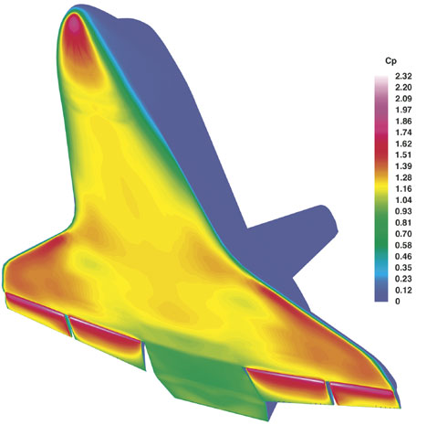
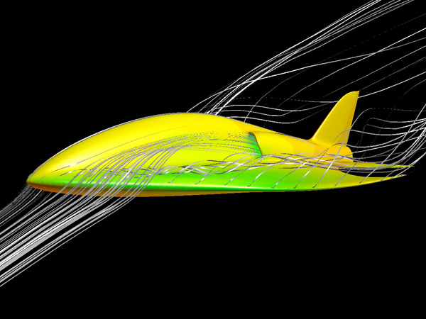
One approach is to discretize the spatial domain into small cells so every single cell can be computed separately. Using this method one gets a mesh grid of the definite fluid motion. Figure 2 shows how such a mesh grid looks like in practice. NASA is testing complex scenarios of its space shuttles like return-to-launch-site and transatlantic abort maneuvers by the use of computational fluid dynamics. The image shows the surface pressure distribution at the speed of Mach 15. Figure 3 shows another shape of how computers can be used for flow visualization. | |||
== References == | == References == | ||
*[Merzkirch, 1987] Wolfgang Merzkirch. ''Flow Visualization, Second Edition''. Academic Press Inc. Ltd., London, 1987. | *[Merzkirch, 1987] Wolfgang Merzkirch. ''Flow Visualization, Second Edition''. Academic Press Inc. Ltd., London, 1987. | ||
*[Devenport and Hartwell, 2006] W.J. Devenport and W.L. Hartwell, Experiment 1 - Flow Visualization. Last modified at: December 20, 2006. Retrieved at: November 9, 2007. [http://www.aoe.vt.edu/~devenpor/aoe3054/manual/expt1/index.html http://www.aoe.vt.edu/~devenpor/aoe3054/manual/expt1/index.html]. | *[Devenport and Hartwell, 2006] W.J. Devenport and W.L. Hartwell, Experiment 1 - Flow Visualization. Last modified at: December 20, 2006. Retrieved at: November 9, 2007. [http://www.aoe.vt.edu/~devenpor/aoe3054/manual/expt1/index.html http://www.aoe.vt.edu/~devenpor/aoe3054/manual/expt1/index.html]. | ||
* [Löffelmann, 1998] Helwig Löffelmann , Visualizing Local Properties and Characteristic Structures of Dynamical Systems, Created at: November, 1998. Retrieved at: November 5, 2009 http://www.cg.tuwien.ac.at/~helwig/diss/ | |||
== External Links == | == External Links == | ||
*[http://en.wikipedia.org/wiki/Flow_visualization http://en.wikipedia.org/wiki/Flow_visualization] | *[http://en.wikipedia.org/wiki/Flow_visualization http://en.wikipedia.org/wiki/Flow_visualization] | ||
*[http://en.wikipedia.org/wiki/Computational_fluid_dynamics http://en.wikipedia.org/wiki/Computational_fluid_dynamics] | *[http://en.wikipedia.org/wiki/Computational_fluid_dynamics http://en.wikipedia.org/wiki/Computational_fluid_dynamics] | ||
*[http://www.ilight.com/ FieldView, a software for simulating, streamlines around a solid surface] | |||
Latest revision as of 15:01, 25 November 2009
Flow visualization is a process of making the physics of fluid flows visible in oder to analyse it.
Definition[edit]
Overview[edit]
Flow visualization is a modern technique to visualize motions and patterns of mostly invisible fluids, e.g. gas, air or water. Main target is to make flows in a specific context visible so that it can be analyzed.
Although the basic task for flow visualization is revealing the flow within fluids, it may offers an additional benefit. It does not only make flows visible, it can also be used as a method for simulating flows and the interaction of objects within fluids. So it is also a simulation technique and therefore, it can be classified as a method for Scientific Visualization.
Application areas for flow visualization are e.g. in aviation, aqua- or aerodynamic.
In fact, there are several ways how to do this. Generally we can divide into two main classes of methods:


Physical methods[edit]
Physical methods are an experimental approach on flow visualization. Basically these techniques can further be divided into three groups [Löffelmann, 1998]:
- Adding foreign material
- These methods work by adding small particles, e.g. smoke or oil, to the fluid to make it visible. Figure 1 gives an example for using smoke in a wind tunnel.
- Optical techniques
- These methods work e.g. with the refraction of the light or by working with light beams, where images with shadows and caustics indicate flows.
- Adding heat or energy
- These methods use e.g. gas, where the molecules have been excited by shooting electrons at them, to visualize motion patterns.
The main disadvantage of physical methods is that these techniques require a test system (e.g., a wind tunnel) and therefore, may be limited by physic constraints (e.g., the size of the tunnel) and costs.
Computational methods[edit]
In contrast to physic methods, the motion of fluids can also be expressed by mathematical equations which can be estimated numerically. Thus even supercomputers would take a long time to solve the equations and the solution would only be an estimation of the definite problem, more accurate methods needed to be discovered.
One approach is to discretize the spatial domain into small cells so every single cell can be computed separately. Using this method one gets a mesh grid of the definite fluid motion. Figure 2 shows how such a mesh grid looks like in practice. NASA is testing complex scenarios of its space shuttles like return-to-launch-site and transatlantic abort maneuvers by the use of computational fluid dynamics. The image shows the surface pressure distribution at the speed of Mach 15. Figure 3 shows another shape of how computers can be used for flow visualization.
References[edit]
- [Merzkirch, 1987] Wolfgang Merzkirch. Flow Visualization, Second Edition. Academic Press Inc. Ltd., London, 1987.
- [Devenport and Hartwell, 2006] W.J. Devenport and W.L. Hartwell, Experiment 1 - Flow Visualization. Last modified at: December 20, 2006. Retrieved at: November 9, 2007. http://www.aoe.vt.edu/~devenpor/aoe3054/manual/expt1/index.html.
- [Löffelmann, 1998] Helwig Löffelmann , Visualizing Local Properties and Characteristic Structures of Dynamical Systems, Created at: November, 1998. Retrieved at: November 5, 2009 http://www.cg.tuwien.ac.at/~helwig/diss/